
[1]
This article explains why a new approach is needed for the safety assessment of the major operational and technology changes that are planned for introduction into European ATM up to 2020 and beyond. This approach has to satisfy two conditions: firstly it has to be much broader than that traditionally followed in ATM in that it must address the positive contribution that a fully functioning ATM service makes to aviation safety and not just consider the negative effects that failures within the ATM system might have on the risk of an accident; and secondly, rather than rely simply on current, process-based safety-assessments, it must be based on a framework which, in accordance with European safety regulatory requirements, requires that correct and complete arguments be established to demonstrate that the overall ATM System, as well it constituent parts, are (and will remain) tolerably safe. The article presents the theoretical basis for satisfying these two conditions it explains from first principles how current techniques such as Fault Tree Analysis can be adapted to model ATMs positive, as well as negative, contribution to aviation safety, and describes how a rigorous safety argument can be derived from sound systems-engineering principles and be used to drive the whole safety assessment / assurance process. The article also gives an overview of how these principles were developed for application to the safety assessment of ATM development projects within the scope of SESAR - the Single European Skies ATM Research programme, equivalent to the US NextGen programme. This approach has already been applied by EUROCONTROL to a number of safety assessments including enabling projects for SESAR.
[1] Derek Fowler and Ron Pierce are with JDF Consultancy LLP, UK: derek@jdf-consultancy.com. Eric Perrin is with EUROCONTROL, France.
This article originally appeared in ATCA's ATC Quarterly
European airspace is fragmented and will become increasingly congested as traffic is forecast to grow steadily over the next 10 years or so. ATM services and systems are not sufficiently integrated and are based on overstretched technologies. Therefore, in order to meet future air traffic needs, the European ATM services must undergo a massive operational change, enabled and supported by innovative technologies.
SESAR - the Single European Sky ATM Research Programme, equivalent to the US NextGen programme - is the means of delivering the required operational and technological changes, by the year 2020.
The early safety work on SESAR came to three very important conclusions:
- that in order to meet forecast demand, the capacity of the European ATM system would need to increase by 1.7-fold by 2020 [SESAR, 2006]
- that for most ATM-related accident types, the risk of an accident per flight would need to reduce by 3-fold i.e. the square of the traffic increase [EUROCONTROL, 2008]
- merely improving the reliability / integrity of the current ATM system would not make significant inroads into the required safety improvement additional functionality and improved performance of existing functions would also be required.
In 2008-09, as part of this early work for SESAR, EUROCONTROL Brétigny undertook an initial, a priori safety assessment of the SESAR Concept of Operations, in order to:
- develop a safety assessment methodology that would be suitable for the SESAR programme
- apply it, as far as practicable in the time available, in order to validate its completeness and correctness and to investigate the degree and extent to which the SESAR Concept of Operations had the potential to be at least tolerably safe.
The first major problem for this initial SESAR safety assessment was that, for reasons explained in the next section, most (if not all) extant ATM safety assessment methodologies focused almost entirely on proving the reliability and integrity of ATM systems by analysing what could go wrong within those systems - with very little attention paid to system functionality and performance and what needs to go right! What was needed, therefore, was what became known as the broader approach to safety assessment.
The second major problem was the sheer complexity of the SESAR Concept, the evolutionary nature of its implementation (the phased introduction of more than 180 distinct operational improvement steps) and the dispersed and disparate nature of the many different organisations contributing to the SESAR Programme. What was needed, therefore, was a common framework for safety assessment; since this was based on a safety argument it became known also as the argument-driven approach to safety assessment.
Clearly, as with any safety process, the safety assessment approach for SESAR has to be soundly based from a theoretical perspective, as well being pragmatic and of maximum benefit to SESAR Stakeholders.
This article, therefore, explains the theoretical basis for the broader, argument-driven approach to safety assessment and then shows, at a relatively high level, how it is intended to be applied to the SESAR Operational Concept circa 2020.
Safety-related Systems - Principles
Consider the two types of safety-related system shown in Figure 1.
In case (a) we have a system - say, a complete nuclear power plant - which simply provides a service into its operational environment. Because the service in the example is the provision of electrical power then, from a purely safety viewpoint, we do not care whether the service is provided or not. What we do care about are the hazards (e.g. radiation leakage), and the related level of risk, that a failure internal to the system might present to its operational environment (including the people therein).
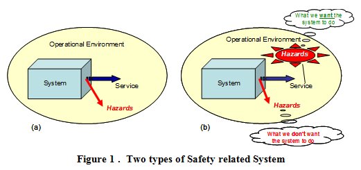
Of course, we must also remember that the introduction of the case (b) system in order reduce pre-existing risk would bring with it some additional, system-generated hazards / risk due to internal failure of the system, as in case (a).
As we will see below, what is very important about Figure 1 is that the mitigation of pre-existing hazards / risks (what we want the system to do) and the inevitable introduction of system-generated hazards / risks (what we dont want the system to do) depend on entirely different properties of the system.
To illustrate the importance of distinguishing correctly between these two types of safety-related system, take the example of a car airbag for which, for the sake of this discussion, we wish to make a safety case. If we were to simply follow a purely failure-based approach, we would start (at the wrong point, as we will see shortly) by identifying the hazards presented by the airbag, which are caused by its two main failure modes i.e. failure to operate when required, and operating when not required. We would then take (or, if necessary, develop) a risk classification scheme and use it to derive safety requirements that specify the frequency with which those failures could be allowed to occur. Even if the results were valid, they would lead us only to:
- an understanding of how reliable the airbag needs to be - so that it operates when required; this would, however, not give any assurance that, when it did operate, the airbag would actually protect the front-seat occupants from death or serious injury in the event of a collision
- and the irrational conclusion that putting an airbag in a car would increase the risk of death or serious injury to the front-seat occupants, because of the finite (albeit small) possibility that it would operate when not intended to!
So without any evidence of a safety benefit from the airbag - rather, only the possibility of actually being killed / seriously injured by it - we would have no case for fitting one.
If instead we were to take a more rational view, rather than simply follow a procedure, we would start from the point that in the event of, say, a head-on collision without an airbag there is a very high risk of death or serious injury to the front-seat occupants of a car. This risk we can call pre-existing because, by definition, it is inherent in driving and has nothing whatsoever to do with the airbag indeed it is to mitigate this risk that we are intending to fit the airbag in the first place.
So, our safety assessment would now comprise:
- firstly, a success approach in which we assess how effective the airbag would be when it did work i.e. by how much the pre-existing risk would be reduced by the airbag - and what properties of the airbag determine the amount of this reduction; and then
- a failure approach in which we assess the system-generated risk, induced by airbag failure or misuse.
Thus, given the correct set of functionality & performance properties e.g. shape, location, strength, compressibility, sensitivity to g forces, speed of deployment etc as well as adequate reliability properties, our safety case should show that the airbag would make a positive contribution to the reduction in the identified pre-existing risk that is very much greater than the system-generated risk due to airbag failure.
Of course, we also need to remember the human aspects. For example, the success case could be significantly undermined if, for example:
- the drivers driving behaviour were modified by the assumption that the airbag would always provide adequate protection in the event of a collision, thus increasing the pre-existing risk, and / or
- the front seat occupant(s) neglected to use seat belts , and / or
- a small child was placed on the front seat without airbag operation being automatically (or manually) inhibited.
Taking full account of such human factors, what would emerge from this success & failure approach would be a much more balanced, reasoned and rational conclusion than the one that would emerge from considering only airbag failure.
Furthermore, since the net reduction in risk provided by the airbag - i.e. the aggregate of its success and failure contributions - needs to be substantially positive, it means that not only would the failure approach be incomplete without the complementary success approach, it is also dependent on it - in other words, we cannot define failure until we have fully defined success.
Is there a Problem in Practice?
Given that the distinction between what we want the system to do and what we dont want the system to do seems obvious, it would be reasonable to ask whether there is actually a problem here and if so why?
Professor Nancy Leveson of MIT gives us an insight into this question in a paper [Leveson, 2001] about her review, for the US DoD, of major software-related accidents and the implication for software reliability. Her paper presents compelling evidence that software reliability had never been the cause of such disasters - on the contrary, in every case that she investigated, the software had performed in exactly the manner that it was designed to. The problem was that the software was designed to do the wrong thing for the circumstances under which it failed (or, as in the case of Ariane V) was used for a purpose different from that for which it was originally designed.
Professor Leveson quite rightly, therefore, poses the question as to why, in most software safety standards, so much emphasis is placed on processes to improve software reliability whilst not ensuring that the resulting systems actually perform the intended function i.e. allowing them to be what one might call reliably unsafe. Therefore, we need to consider whether this problem with safety standards (or the way in which they are applied) is evident also at the system level, in the ATM sector.
A Suitable Standard for ATM System Safety Assessment
When EUROCONTROL initiated the development of its own safety assessment methodology (SAM) [EUROCONTROL, 2007] about 14 years ago it decided, not unreasonably at the time, to use the SAE standards for the certification of aircraft systems (ARP 4754 [SAE, 1996a] and its safety assessment counterpart ARP 4761 [SAE, 1996b]), as the starting point.
The way in which these two standards work together in the civil aircraft sector is illustrated in Figure 2.
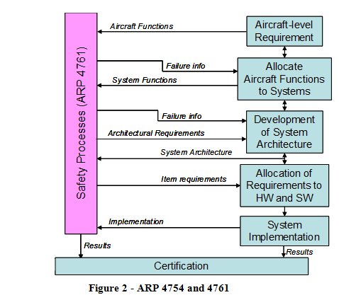
The safety assessment processes of ARP 4761 take information from the ARP 4754 system-development process, analyses it and feeds the results (in the form of failure information and the corresponding safety requirements) back into the system development.
What is significant here is that:
- ARP 4761 is concerned only with failures in the systems that are developed under ARP 4754 - this works because what we want the systems to do (i.e. its required functionality and properties) is addressed within the scope of ARP 4754
- unlike in the rest of this article, ARP 4754 excludes the human operators (flight crew) from its definition of system, and therefore from the Aircraft Certification process, since they are addressed as part of the subsequent, but quite separate, Operational Approval process.
The reason that these two points are significant is that the EUROCONTROL SAM [EUROCONTROL, 2007] was derived and adapted mainly from ARP 4761, without the benefit of an ATM equivalent to the rigorous systems-engineering processes of ARP 4754. In most ATM safety assessments, therefore:
- the focus was on equipment failure (and hence on equipment reliability), not on the safety properties of the functions which the equipment was required to perform, and
- the human aspects were treated as operational (rather than safety) matters.
For many years, this worked quite well because the main purpose of the ATM equipment was simply to provide information to the human operator (i.e. the Controller) in whom most of the functionality of the overall ATM system was vested.
Over recent years, however, it has become increasingly clear that this position is not sustainable in the face of increasing automation, and the increasingly integrated nature, of the ATM system both ground-based and airborne elements. So, if ARP 4761 is no longer appropriate, what would be a suitable safety standard on which to base ATM safety assessments for something as highly automated and integrated as SESAR?
The answer could lie in International Electrotechnical Commission standard IEC 61508 [IEC, 2010], a widely recognised international standard on functional safety, which is based on the application of good systems-engineering practice to safety assessment. At its core lies a Figure 1 case (b) view of safety-related systems in that it defines (implicitly, at least) a safety-related system (SRS), not as something that merely poses a threat, but rather as something that makes a net positive contribution to the safety of its operational environment (or host system). It uses the term Safety Functions to describe an abstract, functional representation of an SRS and it is the realisation of these functions that make the required positive contribution to safety - what IEC 61508 calls necessary risk reduction.
We can use our simple example of a car airbag to explain, and develop, the above principles since, as we saw above, an airbag perfectly fits case (b) of Figure 1 and can be considered to be a Safety Function in the context of IEC 61508.
Figure 3 shows the risk (to the front-seat occupants) with and without the airbag i.e. RP and RA, the pre-existing and achieved risk, respectively. The safety case for the airbag depends on its saving far more lives / preventing more serious injury, when operating as intended (represented by the right-to-left arrow) than on any deaths / serious injury that might be caused in the event of its failure to operate, spurious operation or misuse (represented by the solid left-to-right arrow).
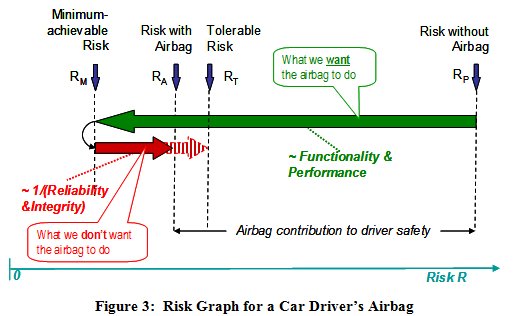
- RP has nothing to do with the airbag thus it is the pre-existing risk, as above
- RM ,is the theoretical minimum risk that would exist in the complete absence of failure / spurious operation (including misuse) of the airbag it is not zero, because there are some accident scenarios for which an airbag cannot provide mitigation
- the risk increase RA-RM is caused entirely by the failure / spurious operation of the airbag, described above - thus it is the system-generated risk
- the safety case for the airbag is based on showing, at least qualitatively, that RAP
- if we now introduce RT, the maximum tolerable level of risk, then an interesting conclusion emerges: given that RT is fixed (e.g. by a regulatory body), then the maximum tolerable failure rate of the airbag - i.e. the length of the extended l-r arrow (RT-RM) - depends on the length of the r-l arrow (RP-RM); in other words, the tolerable failure rate depends on how successful the airbag is in reducing the pre-existing risk in the first place
- RP-RT equates exactly to the concept of necessary risk reduction in IEC 61508
- if, as we desire, RA-RMP-RM, then the overall risk actually achieved (i.e. RA) is much more sensitive to changes in the length of the r-l arrow (i.e. to changes in functionality and performance) than to proportionate changes in the length of the l-r arrow (i.e. to changes in reliability & integrity) .
IEC 61508 has been designed to be applied to (or, where necessary, specifically adapted for) a wide range of sectors currently this includes process, rail, and automotive industries. As far as the authors are aware, it has not been applied in the same way to ATM although, as will become apparent in this article, the approach taken on the initial SESAR safety assessment has much in common with the basis of IEC 61508 and could eventually pave the way for its full adaptation to ATM; the latter would properly be a decision for the main SESAR Programme - for now, we need to consider only how the above basic principles could be applied.
Modelling ATM Risk
ATM is somewhat wider in scope and complexity than a car airbag but the same, fundamental principle holds good i.e. its primary purpose is to mitigate pre-existing (aviation) risk.
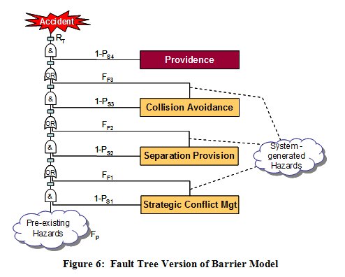
This can be illustrated by expressing the three layers of ATM, described in the ICAO Global ATM Concept [ICAO, 2005], in the form of a Barrier Model (derived from James Reasons Swiss Cheese model [Reason, 2000]) as shown in Figure 4.
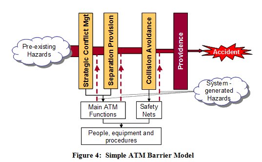
Since these risks (or hazards) are inherent in aviation and can therefore be considered as pre-existing as far as ATM is concerned, they form the input to the model.
The barriers act in rough sequence from left to right and effectively filter out a proportion of the pre-existing hazards. The final barrier reflects the point that, even when all three layers of ATM have been unable to remove a hazard, there is a (usually high) probability that an actual accident will not result.
As the main barriers are provided by the elements of the ATM system, it is the ATM system functionality & performance that determines the effectiveness of the barriers in removing the pre-existing hazards. Of course, elements of the ATM system can fail to operate, or operate spuriously / incorrectly, giving rise to system-generated hazards, as defined above these are shown in Figure 4 as inputs at the bottom of the model.
An alternative way of expressing this is by means of the risk graph shown in Figure 5. What is crucial about Figure 5 is that, in order to show that ATM achieves a tolerable level of risk overall, we need to understand the relationship between pre-existing risk (Rp), the positive and negative contribution of each of the three Barriers, and the positive contribution of Providence .
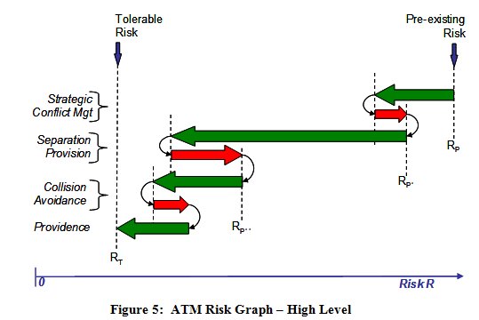
- the pre-existing (aviation hazards) and their frequencies (FP) - i.e. the pre-existing risks
- the probability of success (PSn) of each barrier in mitigating those risks, and
- the frequency (FFn) with which failure of each barrier introduces new, system-generated hazards / risks.
Alternatively, of course, if we make the top-level risk our target (RT) then, given FP and access to historical accident and incident data, we can make informed judgements about what PSn and frequency FFn are required to be in order to satisfy RT.
Thus the model captures the positive, as well as the negative, contributions of ATM to aviation safety, and it is this form of risk model on which the EUROCONTROL Integrated Risk Picture [EUROCONTROL, 2008] is based and which lies at the heart of the broader approach to safety assessment, although, in practice, the Integrated Risk Picture uses a much more detailed Fault Tree than the one illustrated in Figure 6.
Safety assessments are often done within the context of a safety case. This is consistent with Operational Concept Validation Methodology which is being applied to the non-safety aspects of SESAR, and which also takes a case-based approach.
Like a legal case , a safety case comprises two main elements:
- a set of arguments - i.e. statements which claim that something is true(or false), together with
- supporting evidence to show that the argument is valid.
Safety arguments are normally set out hierarchically; this is shown, using goal-structuring notation (GSN), in Figure 7.
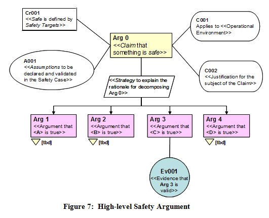
GSN is simply a graphical representation of an argument / evidence structure. In safety work, it usually starts with the top-level claim (Arg 0) that something is (or will be) safe; this is then decomposed such that it is true only if, and only if, the next-level argument statements (in this case Arg 1 to 4) are all true.
The strategy text should explain the rationale for that decomposition, and the claim is supported by vital contextual information, as follows:
- what is meant by safe is defined by means of safety targets, which may be quantitative and / or qualitative (Cr001)
- the context for the claim must include a description of the operational environment for which the claim is being made (C001); the sub-section below on Requirements Engineering explains how critical this is to the validity of the claim
- assumptions (A001) are usually facts on which the claim depends and over which the organisation responsible for the safety case has no managerial control - e.g. traffic will increase by x% per year
- if the claim relates to a major change to a safety-related system, it is good practice to provide a justification (C002) for
that change.
The arguments would then be further sub-divided until a level is reached at which a piece of documented evidence (Ev001), of a manageable size, could be produced to show that the corresponding argument is valid. Guidance on constructing safety arguments is given in [EUROCONTROL, 2006].
What next has to be addressed is how to derive a complete and rigorous safety argument on which to base the safety assessment process for this, we turn to good requirements-engineering practice as follows.
Requirements Engineering and the Safety Argument
Capturing a complete and correct set of safety requirements is as fundamental to any a priori safety assessment as requirements engineering is to systems engineering in general. For the initial SESAR safety work, therefore, we adopted the simple, but rigorous, requirements-engineering (RE) model, adapted from [Jackson, 1995], shown in Figure 8.
In this model, systems exist in the real world. The part of the real world that influences the system, and into which the system provides a service, is known as the application domain. Users of the service exist in the application domain. The system interacts with the application domain through an interface (i/f) and it is, therefore, across this interface that the service is provided.
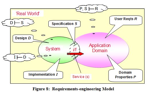
A specification is what the system has to do across the interface in order that the user requirements can be satisfied - i.e. a specification takes a black-box view of the system.
Design, on the other hand, describes what the system itself is actually like and includes all those characteristics that are not directly required by the users but are implicitly necessary in order for the system to fulfil its specification and thereby satisfy the user requirements. Design is essentially an internal, or white-box, view of the system. For ATM, design is slightly complicated by the fact that parts of the system lie in the aircraft - i.e. in the application domain.
Implementation is building and proving the physical system in accordance with the Design.
The formal notation in the bubbles in Figure 8 defines three relationships that must be shown to be true:
- that the Specification S satisfies the user requirements R. However, this can be true only for a given set of properties P of the application domain and if any one of these three sets of parameters is changed then requirements-satisfaction demonstration is invalidated until one of the other sets is also changed, in compensation - this is expressed as P, S |- R
- that the Design D satisfies the Specification S - i.e. D |- S
- that the Implementation I satisfies Design D - i.e. I |- D.
The distinction, and relationship, between user requirements, specifications, domain properties, design and implementation are not merely academic niceties; rather, they provide the essential foundations for developing systems that do, and can be shown to do, everything required of them.
In our argument-based approach we use them directly as safety arguments thus:
Arg 1 - the system has been specified to be safe - for a given set of user requirements and in a given application domain (hereafter referred to as the operational environment)
Arg 2 - the system design satisfies the specification
Arg 3 - the implementation satisfies the design
Then, by adding two further arguments:
Arg 4 - the transition from current system to the new (or modified) system will be safe i.e. the known risks during this process have been reduced as far as reasonably practicable - and
Arg 5 - the system will be shown to operate safely throughout its service life
we have a sufficient, high-level safety argument structure for developing a new or modified system, bringing it into service and maintaining it through its operational life.
Safety Assurance
There are two problems with the simple argument / evidence approach described above.
The first is that, in itself, it gives no i indication how the evidence should be obtained or how rigorous that evidence needs to be.
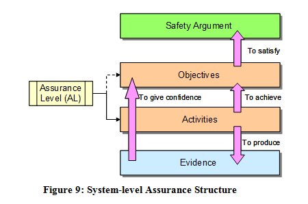
- safety assurance objectives, which state what has to be achieved in order to satisfy the related strand of the argument, and
- safety assurance activities which state how the safety assurance objectives will be satisfied including the tools and techniques etc to be used.
The output of the assurance activities is then the evidence that is needed to show that each safety assurance objective, and in turn each branch of the safety argument, is satisfied.
In many assurance-based approaches, the objectives and activities are, to some degree and extent, determined by an assigned assurance level (AL) these ALs are usually derived by assessing the consequences of failure of the system element under consideration.
For the initial SESAR work, we decided to make the activities independent of the ALs and give only general guidance on the rigour required of the tools, techniques etc used in the safety assessment. This was because we did not feel at the time that we had the competence or legal authority to be prescriptive about this therefore it was left to individual safety assessments / safety cases to justify that the evidence produced is trustworthy (see, for example, Arg1.4 below).
The second problem that safety assurance is also often used to address, concerns the safety-integrity of system elements - software functions and human tasks, in particular. Whereas it may be necessary to specify Safety Integrity Requirements for all elements of a system in order to show compliance with a numerical Safety Target, it is usually very difficult to show in a direct way - through, for example, test results - that such requirements are actually satisfied in implementation. It therefore becomes necessary to adopt a more indirect, assurance-based approach, which uses the rigour of the development processes to give confidence that the requirements are likely to be / have been satisfied. This is reflected in, for example, airborne software standard DOD 178B [RTCA, 1992] and IEC 61508 [IEC, 2010], both of which are assurance based.
The EUROCONTROL SAM [EUROCONTROL, 2007] has also adopted an assurance approach in the safety assessment of the individual software, procedure and (under development) human elements of ATM systems but the application to the overall system, as described herein, is a new addition.
Safety Argument and the Project Safety Lifecycle
The essence of the argument-driven approach is illustrated at the highest level in Figure 10.
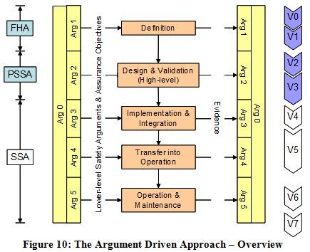
The key point about this diagram is that it is the needs of the argument (i.e. the generation of evidence) that drive the processes - not the other way around. In other words, it is not the process that determines the argument; rather the argument must be directly about the product for which the argument is being made, and the lifecycle process contains only those activities that are necessary to support this product-based argument.
APPLICATION TO SESAR SAFETY ASSESSMENT - OVERVIEW
This section explains in general how the above theory and principles were developed for application to the initial safety assessment of the SESAR operational concept, circa 2020.
The High-level Safety Argument
A typical high-level safety argument for SESAR is shown in Figure 11, using the En-route phase of flight as an example.
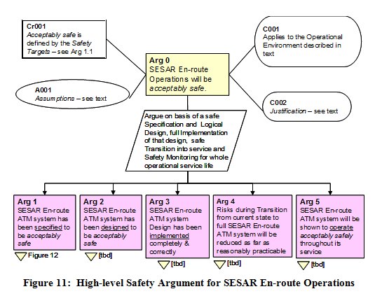
A key assumption at this stage is that SESAR will deliver by 2020 a 1.7-fold increase in capacity [SESAR, 2006] and that this will be fully taken up by a corresponding increase in traffic levels.
The justification (C002) for SESAR stems from its benefits to the airspace users, which include improvements in the capacity, cost-effectiveness, efficiency, environmental sustainability, and flexibility of the overall ATM service.
The claim is then decomposed into the 5-part argument structure as derived above.
The rest of this article addresses the Definition Phase (Arg 1) and the Design & Validation Phase (Arg 2) since these are the focus of the initial safety work on SESAR. In both cases, given the practical limitations of an article such as this, it is possible to present only the higher levels of the safety argument and outline examples of the safety assurance activities and techniques for generating evidence to support the argument.
Arguments 3 to 5 reflect normal ATM safety practice and need to be satisfied by the organisation(s) responsible for implementation of the design (Arg 3) and the subsequent SESAR En-route operations (Arg 4 and 5). If a change is deployed in a phased manner (as is definitely the case for SESAR) then this would need to be addressed under Arg 4 i.e. the safety of each stage of the deployment of would need to be assessed in addition to the safety of the circa 2020 end system, taking account of the fact that developments in adjacent airspace may be being deployed in a different sequence and/or to different timescales it is part of the current SESAR work to consider how to address that problem.
Definition Phase
Decomposing Arg 1 - Specification
In order to decide how to decompose Arg 1, we can make further use of the Requirements Engineering model in Figure 8 as follows. This results in the structure shown, in GSN form, in Figure 12.
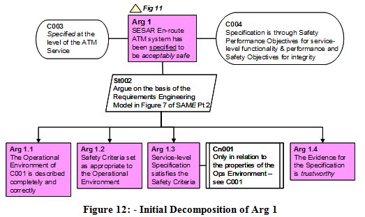
Next, we make an argument (Arg 1.2) that the Safety Targets are appropriate and correct for that environment. For the initial SESAR work, we identified three types of safety target, for each of the four main phase of flight:
#1 the risk of an ATM-related accident (per annum) shall be no higher than pre-SESAR
#2 the risk of an ATM-related accident shall not exceed [tbd] per flight hour
#3 the risk of an ATM-related accident shall be reduced as far as reasonably practicable
Then, we make an argument (Arg 1.3) that the ATM service-level Specification will satisfy the Safety Targets (given the Operational Environment Properties) - note, in particular, the constraint (Cn001) on Arg 1.3 in order to fully capture the P, S I R relationship of Figure 8.
Finally, we make an argument (Arg 1.4) that the evidence supporting Arg 1.1 to 1.3 is trustworthy - i.e. can be relied upon - from three perspectives: the processes, tools and techniques employed; the correct application of those processes etc; and the competence of the people involved. The level of confidence that is required here is determined by the Assurance Levels mentioned in the Safety Assurance section above.
Thus we have a complete argument, at this stage, that the system, at the level of the ATM service, has been specified to be acceptably safe.
Definition Phase Lifecycle Activities
Early experience of applying the above approach to enabling projects for SESAR has shown that a lot can be obtained in terms of a safety validation of individual operational concepts by applying a more detailed analysis process at the ATM service level, as outlined in Figure 13, and described thereafter using the context of Terminal Area operations as an example.
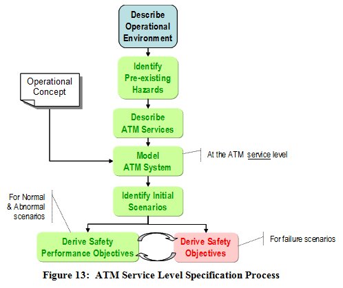
The process starts with a detailed description of the Operational Environment for the scope of the safety assessment. For Terminal Area operations it would include typically:
- airspace structure and boundaries
- types of airspace / ICAO classifications
- route structures (as applicable) and any restricted airspace (temporary or otherwise)
- airspace users e.g. commercial jets, military aircraft (flying as OAT), general aviation, very-light jets, unmanned aerial vehicles etc
- flight rules IFR and/or VFR and/or OAT
- traffic levels and complexity
- aircraft ATM capabilities
- significant weather and other meteorological conditions
- local terrain features, obstacles etc
- environmental constraints
- separation minima (stating whether they are existing or proposed).
- all adjacent airspace / operations, including En-route and Aerodromes
Pre-existing Hazards
For Terminal Area operations, the pre-existing hazards will normally include the following:
- a situation in which the intended trajectories of aircraft would lead to a mid-air collision
- controlled flight towards terrain or obstacle
- penetration of restricted airspace for military danger areas, this category is quite distinct from mid-air collision since the end effect could be being shot down
- wake vortex encounters
- encounters with adverse weather.
ATM Services
Next we need to describe in detail the ATM services, related to the subject operational concept, and link them to the pre-existing hazards. For example, for arrival traffic in Terminal Areas we might have the following:
- provide separation within particular arrival flows
- provide separation from other flows
- provide separation from terrain/obstacles
- prevent entry into unauthorized areas
- avoid wake-vortex encounters
- avoid adverse-weather encounters.
All these services are needed in order to mitigate the hazards listed above, and have to be accomplished while integrating arrival flows efficiently into a landing sequence to the runway.
In describing the ATM services, in relation to the pre-existing hazards, it is important to explain to whom (i.e. to which airspace users) the services are provided, according to (for example) the types of user, the flight rules (IFR, VFR, OAT etc) and the class of airspace concerned.
Modelling the ATM System at the Service Level
The next stage is to explain how the above services are delivered by the ATM system, at the service level. Clearly, this must fully reflect the operational concept at this level, as indicated in Figure 13.
For some operational concepts, the system can be modelled very effectively at the service level by means of a Barrier Model - for example, a more detailed version of that discussed above. In other cases a different form of model may be appropriate - for example the use of an airspace model for the safety assessment of P-RNAV arrival routes in Terminal airspace.
Identifying the Initial Scenarios
Scenarios are used initially to expand on, and analyse, the service-level model of the ATM system in order to facilitate the derivation of Safety Performance Objectives - see below. Such scenarios must fully reflect the Operational Concept and must include:
- all normal conditions of the operational environment - i.e. those that the system is expected to encounter in day-to-day operations
- all abnormal conditions of the operational environment - i.e. those that the system may encounter, exceptionally.
Deriving the Safety Performance Objectives
From the description of the services delivered by the ATM system, in order to mitigate the pre-existing risks sufficiently to meet the Safety Targets, the Safety Performance Objectives capture formally the essential safety properties of the system to ensure that they are fully incorporated in the subsequent design and implementation of the system.
Whereas the Safety Performance Objectives capture what has to happen at the ATM-service level, for all of the normal and abnormal scenarios, they do not state how this will be accomplished - this is left to the Safety Requirements derived for the subsequent Design of the system.
Deriving the Safety Objectives
In line with ESARR 4 [EUROCONTROL, 2001] (and equivalent European Commission regulations), Safety Objectives are derived in order to the limit the frequency of occurrence of (service-level) system-generated hazards so as to keep the overall risk within the Safety Targets.
This process involves the application of the SAM [EUROCONTROL, 2007] Functional Hazard Assessment at the service level, the two curved arrows in Figure 13 indicating that:
- a good starting point for deriving the failure scenarios is negating the Safety Performance Objectives i.e. asking what if Safety Performance Objective #nn is not achieved
- the mitigations of the consequences of the system-generated hazards are captured as additional Safety Performance Objectives.
To date (2011), the above more-refined approach has been applied very successfully to a very wide range of En-route, Terminal Area and Airport projects including, for example, military UAS operations, merging of arrivals using P-RNAV procedures, the introduction of 8.33 kHz voice channel spacing below FL 195, and the flexible and dynamic use of wake-vortex separations. In all cases it was found that a lot could be deduced about the potential safety impact of a new operational concept before getting into the actual system design.
Design & Validation Phase
Decomposing Arg 2 Logical Design
The next step is the argument (Arg 2) that the ATM system had been designed to satisfy the ATM service-level specification. It is clear that at this stage it would impracticable for the initial safety assessment to attempt a physical design since that would more appropriately be left to individual implementations. Thus it is necessary to find a more generic representation of the system known as a Logical Design - and to argue (Arg 2.1) that this satisfies the Specification.
However, two more issues need to be addressed in order to complete a satisfactory argument for Design:
- to show that the Logical Design is realistic i.e. would be capable of being implemented in a physical system, comprising people, equipment and procedures (Arg 2.2)
- to show that all the evidence under Arg 2 is trustworthy (Arg 2.3).
It is very important to note that making an argument for a Logical Design is not simply a matter of showing traceability of the individual safety requirements (which form part of the design) back to the Safety Performance Objectives / Safety Objectives of the Specification. This would ignore the possibility that the design as a whole might be in someway internally incoherent or that new failure properties could emerge at the design level that were not apparent at the higher, ATM-service level.
Thus it is necessary to show, at the next level of decomposition of Arg 2.1, that:
- the Logical Design has all of the functionality and performance attributes that are necessary to satisfy the (ATM service-level) Specification
- the Logical Design will deliver this functionality and performance under all normal conditions of the operational environment - i.e. those that the system is expected to encounter in day-to-day operations
- the Logical Design is robust against (i.e. work through), or at least resilient to (i.e. recover easily from), any abnormal conditions of the operational environment - i.e. those that the system may encounter exceptionally
- the Logical Design has the safety-integrity attributes that are necessary to satisfy the Specification.
Note that a traditional (i.e. failure-based) approach would have covered the fourth bullet and possibly some of the third bullet and, within that narrow scope, would typically have been focussed mainly on equipment, unlike the broader approach which also includes all human actors as an integral part of the system - see next below.
Definition Phase Lifecycle Activities
Logical Design
A Logical Model is a high-level, architectural representation of the system design that it is entirely independent of the eventual physical implementation of that design.
The Logical Model describes the main human tasks and machine-based functions, and the interactions between them, and explains what each of those actors provides in terms of functionality and performance, and includes both ground-based and airborne elements of the system.
The Logical Model normally does not show elements of the physical design, such as hardware, software, procedures, training etc - nor does it separately represent human-machine interfaces, these being implicit in every link between a human and machine actor.
Functional Safety Requirements are derived for every ground-based element in the Logical Model, from the Safety Performance Objectives that were derived at the ATM-service level in the previous phase. They describe what each element of the Logical Model must do from a safety perspective and, where necessary, what level of performance is required of it. The equivalent safety properties required of airborne elements of the system - e.g. pilot and aircraft equipment performance - that are outside the managerial control of an ATM service provider are usually captured as Assumptions (that must be validated). For example, having shown that P-RNAV capability would be sufficient for a particular ATM application, it would be reasonable for the ATM service provider - having published the requirement for P-RNAV capability in the airspace concerned - to assume that an aircraft that had been specifically declared as being P-RNAV capable would comply with the specific technical and operational requirements of JAA TGL 10 [JAA, 2000].
Design Analysis
Having produced a design that appears to have all the attributes that are necessary to satisfy the ATM service-level Safety Performance Objectives, the three stages of design analysis are intended to:
- prove the correctness and coherency of the design, under all normal conditions of the operational environment that the system is expected to encounter
- assess the robustness and resilience of the design under any abnormal conditions of the operational environment that the system may encounter
- assess the effects of internal failure of the ATM system on the risk of an accident.
The main differences between the first two stages are the scenarios that define the normal and abnormal environmental conditions, and the requirement that in the first case the system must deliver full functionality and performance whereas in the second case the system may degrade somewhat provided it can be shown that any associated risk is very low because of the short duration and / or infrequency of the abnormal conditions. Both stages must examine the behaviour of the system from a static and dynamic perceptive using, for example, Use Case analysis and Real-time / Fast-time simulations, respectively.
The third stage of Design Analysis is effectively a conventional, failure-based approach to what SAM [EUROCONTROL, 2007] and ARP 4761 [SAE, 1996b] refer to as a Preliminary System Safety Assessment and is not covered further in this article.
CONCLUSIONS
A broader and more rigorous approach, than that traditionally followed in ATM, is needed for current and future ATM safety assessments. EUROCONTROL has developed such an approach, the theoretical foundation for which is the application of good systems-engineering practice to safety assessment, within a safety-argument framework.
So far, EUROCONTROL has used the approach, in the definition and design phases, for an initial safety assessment of the overall SESAR Concept circa 2020 and subsequently applied it to much smaller-scale projects, typical of some of the 180 or so individual operational improvement steps that make up the SEAR Programme.
Although not a formal validation as such, the experience to date has shown that, irrespective of the size and nature of the project concerned, what is outlined in this article is well able to meet the specific safety-assessment challenges presented by the major operational and technology changes that are planned for introduction into European ATM over the period up to 2020 and beyond.
Provision has been made in the SESAR Development Phase for further development and refinement of the detailed methods, tools and techniques, within the above framework. Without it, we would have no view of the potential positive contribution of SESAR to aviation safety - rather we would only understand the (negative) contribution of SESAR to aviation risk, from which very limited, and irrational, conclusions about SESAR safety might be drawn.
ACRONYMS
AL Assurance Level
ARP Aerospace Recommended Practice
DOD Detailed Operational Descriptions
GSN Goal-structuring Notation
i/f Interface
IEC International Electrotechnical Commission
NextGen Next Generation Air Transportation System
OAT Operational Air Traffic
RE Requirements-Engineering
SAM Safety Assessment Methodology (EUROCONTROL)
SESAR Single European Sky ATM Research
SRS Safety-related System
REFERENCES
EUROCONTROL, 2001, ESARR 4 - Risk Assessment and Mitigation in ATM, Ed 1.0,
EUROCONTROL, 2006, Safety Case Development Manual, version 2.2,
EUROCONTROL, 2007, Air Navigation System Safety Assessment Methodology (SAM), SAF.ET1.ST03.1000-MAN-01, Edition 2.1
EUROCONTROL, 2008 Episode 3, White Paper on the SESAR Safety Target, D2.4.3-01, 29 September 2008
HMSO, 1990, The Public Inquiry into the Piper Alpha Disaster, Volumes 1 & 2, November 1990, ISBN 0-10-113102-X
ICAO, 2005, Doc 9854, Global ATM Operational Concept, 1st edition
IEC, 2010, Functional Safety of Electrical/Electronic[etc] Safety Related Systems, IEC 61508, 2010 edition
JAA, 2000, Administrative & Guidance Material, Section One: General Part 3: Temporary Guidance Leaflets, Leaflet No 10: Airworthiness and Operational Approval for Precision RNAV Operations in Designated European Airspace, dated 1 November 2000
Jackson M, 1995, The World and the Machine, Proceedings of 17th International Conference on Software Engineering, IEEE, pp283-292,
Leveson N G, 2001, The Role of Software in Recent Aerospace Accidents, 19th International System Safety Conference, Huntsville AL, USA
Perrin E, Kirwan B, and Stroup R, 2007, A Systemic Model of ATM Safety: the Integrated Risk Picture, Proceedings of the 7th US / Europe Seminar on ATM Research & Development, Barcelona, July 2007
Reason J, 2000, Human Error: Models and Management. British Medical Journal, 18 March 2000, http://www.ncbi.nlm.nih.gov/pmc/articles/pmc1117770.
RTCA, 1992, DO-178B / ED-12B, Software Considerations in Airborne Systems and Equipment Certification
SAE International, 1996, ARP 4754, Certification Considerations for Highly Integrated or Complex Aircraft Systems, November 1996
SAE International, 1996, ARP 4761, Guidelines and Methods for Conducting the Safety Assessment Process on Civil Airborne Systems and Equipment, December 1996
SESAR, 2006, Consortium, Air Transport Framework the Performance Target, D2, DLM-0607-001-02-00a, December 2006
AUTHOR BIOGRAPHIES
Derek Fowler, the principle author of this article, was born in Manchester, UK, in 1945. He was awarded a BSc degree in aeronautical engineering by the Royal Air Force College, Cranwell, UK, in 1968 and an MSc equivalent in aerosystems engineering at the same college in 1975.
He served as an engineer officer in the Royal Air Force for 15 years before joining BAe Systems as a consultant engineer, project manager and then Head of the Laser Systems department. In 1990, he moved into the ATM field, with the UK National Air Traffic Services, as a senior project manager and then Deputy Director for Oceanic Systems. His considerable experience in systems engineering and interest in system safety were then combined, in 1998, when he took up successive senior technical positions with two of the UKs leading systems / safety consultancy companies. For the past 8 years he has operated as an independent safety consultant, through his own company, JDF Consultancy. Working under contract for EUROCONTROL, he has provided safety expertise to more than 30 ATM development programmes including leading the initial safety assessment of the SESAR operational concept, at EUROCONTROLs Brétigny facility. He has many papers on ATM safety issues to his credit, most of them on the development of safety engineering techniques to keep pace with the increasingly rapid changes in ATM technology and operations.
He is a Charted Engineer and a Fellow of the UK Institution of Engineering and Technology.
Eric Perrin was born in Saint-Etienne, France in 1969. He was awarded an Engineer degree in Aeronautics and Computer Science from the French Civil Aviation School (ENAC) in Toulouse in 1993.
He has more than 14 years experience of air traffic management, 8 of which have been spent on safety assessment and safety management. He joined EUROCONTROL in 2002 as GPS Ground-Based Augmentation System (GBAS) Manager. Prior to that, he worked as a Project Manager responsible for the design and development of aeronautical mobile communication systems. As EUROCONTROL Safety Assessment and Safety Case Manager, he led a team of safety practitioners at Brétigny, south of Paris, working on a range of short- and medium-term ATM issues. He has made over 50 presentations on aviation technical issues (COM, satellite navigation, safety assessments) to international fora (GNSS, NAVSAT, ESREL, FAA Risk Conference, ATM R&D Seminars, etc.). He currently works on the safety validation of major aviation operational and technical changes and on safety techniques development to keep pace with foreseen air traffic management evolutions, in particular with SESAR, for which he has recently taken on the responsibility for managing the transversal safety work package (WP 16.6.1).
Ronald H Pierce was born in Glasgow, UK in 1948, and studied at the University of Manchester where he gained his BSc and MSc degrees in computer science, the latter by research.
From 1975 to 1993 he worked for a number of the UKs leading software houses, gaining extensive experience in software engineering topics - compilers, program analysis tools and software engineering methods. Since 1993, he has worked as a Principal Consultant for CSE International Ltd in Scunthorpe, UK, specializing in software and system safety assessment for industry domains including ATM, railway control and signalling, and automotive, and has been responsible for the development of a number of safety cases for large-scale ATM projects such as new operations rooms and their associated equipment. He is also a partner in JDF Consultancy and from 2080-2010, worked under contract half of his time for EUROCONTROL Brétigny, including making a major contribution to the initial safety assessment of the SESAR operational concept. He is the secretary of the working group responsible for the maintenance of international functional safety standard IEC 61508 Part 3. He has published a number of papers in software engineering and safety topics and teaches courses in engineering safety management.
He is a Charted Engineer and a Fellow of the British Computer Society.
.png)